Secondary Spectrum Correction in Periscopes
This subject has been summarized on the page “Periscope Optical Design”. It is repeated here and is followed by a new in-depth treatment.
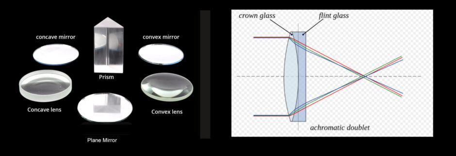
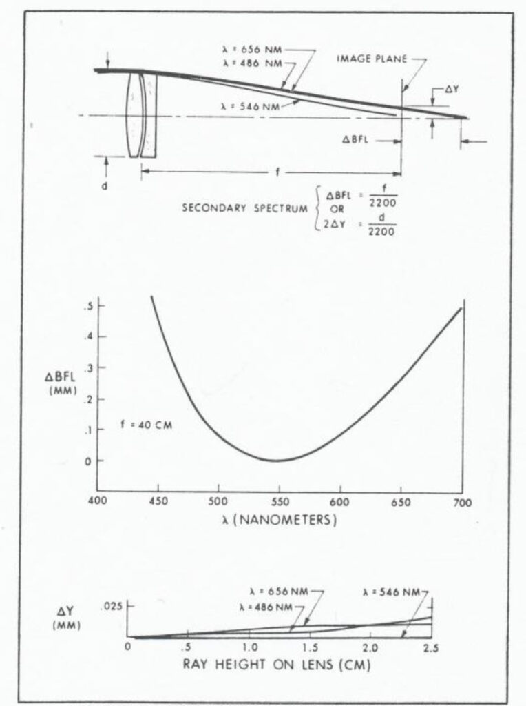
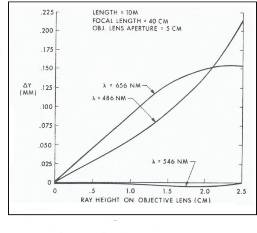
Secondary spectrum is an inherent aberration in ordinary achromatic lenses that precludes achievement of the ultimate achievable resolution. It is especially bad in periscopes since it progressively increases with the passage of light through successive relay lenses, typically, six in number, plus an objective lens.
Secondary Spectrum, Ordinary Doublet
Secondary Spectrum, Typical Periscope
Secondary Spectrum Reduction via Glass Selection
The following graphical means for the selection of glass types for reducing secondary spectrum was presented to Kollmorgen in the late 1960’s by Hank Sijgers, a graduate engineer from Delft University in the Netherlands.
The entire listing of Schott glasses at that time were plotted in terms of their relative partial dispersion deviations from the “normal” line, ∆ Y, versus X, defined as follows:
∆ Y = YN – Y where
YN = 2.2356 X – 0.003539 ,
X = (Ne-Nc) /(Ne-1) and
Y = (Ng – Ne) /(Ne-1)
The secondary spectrum will be corrected when the ratio Y/X is equal for the positive crown element and the negative flint element, i.e., when the plotted points for the two glasses lie on the same Φ line:
Φ = Y/X,
i.e., when the ratio of the relative partial dispersions of the crown and flint glasses are equal.
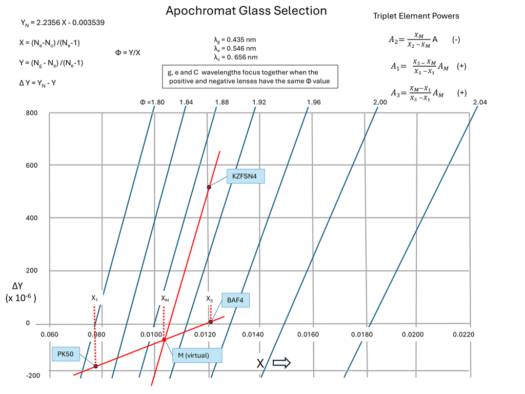
Incorporating a third element allows a “virtual” glass to be synthesized that lies on the same Φ line as one of the real glasses thereby achieving correction of the secondary spectrum.
This is illustrated by the example below comprising lens elements od PK50, KZFSN4, and BAF4 glass types.
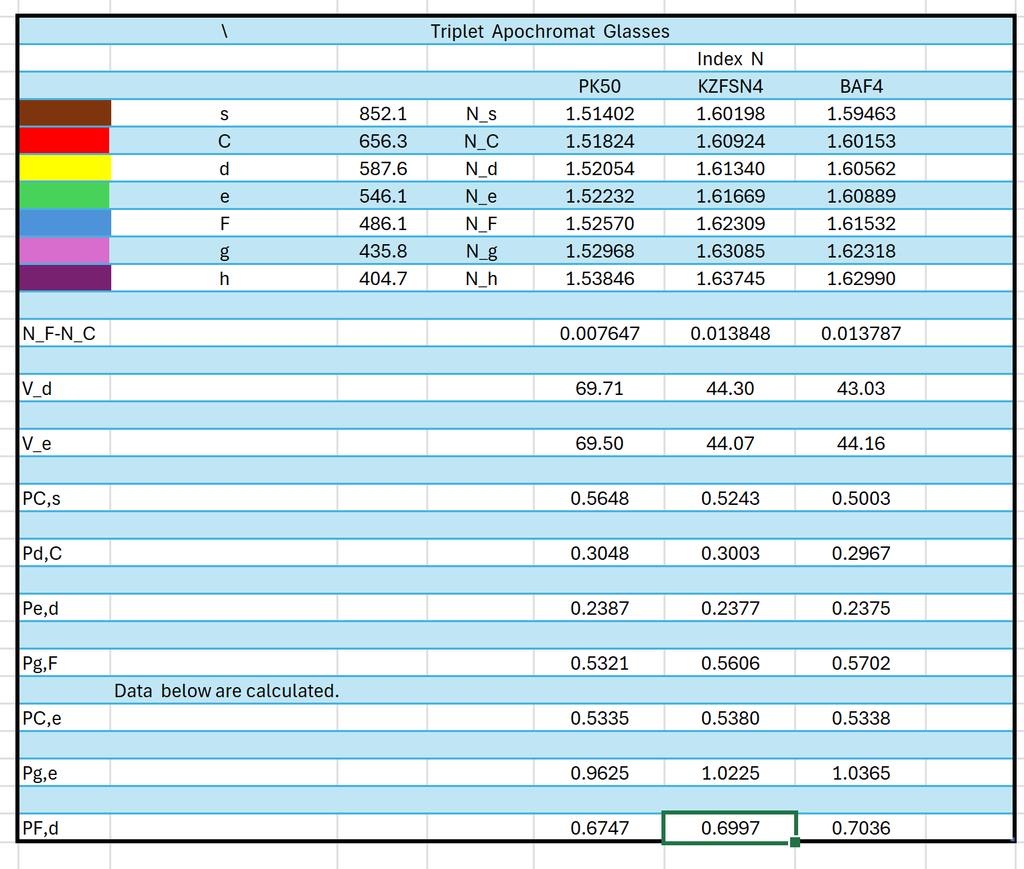
This graphical technique allows potential solutions to be quickly established. and set up for computer optimization with optical design software such as Zemax and CODE V.
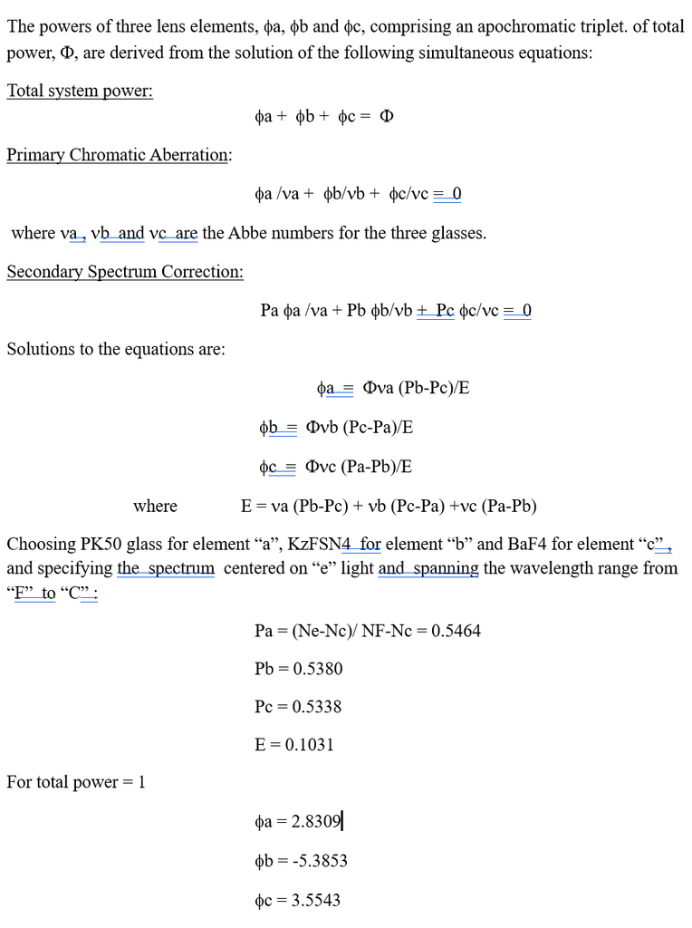
Element powers for the candidate glasses can also be calculated aa shown below,
Apochromat Element Powers
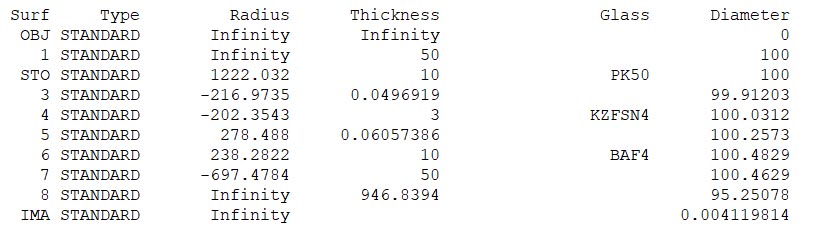
Apochromat Real Lens Design Details
The triplet lens shown below, target EFL = 1000 mm, aperture =100 mm, F-C wavelengfth range waa optimized with a few cycles on Zemax .
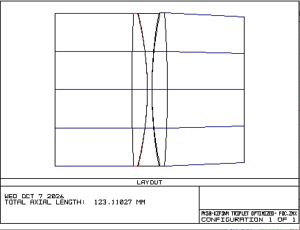
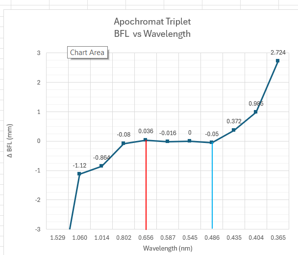
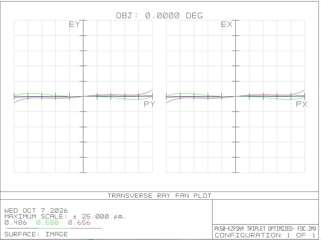
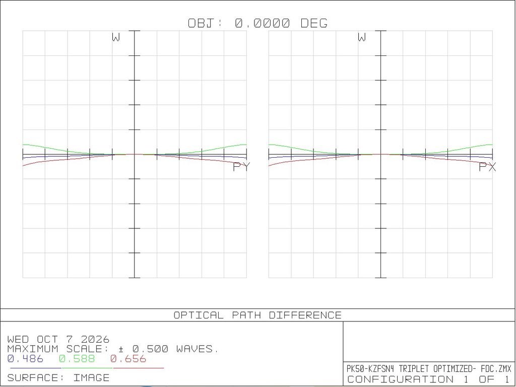
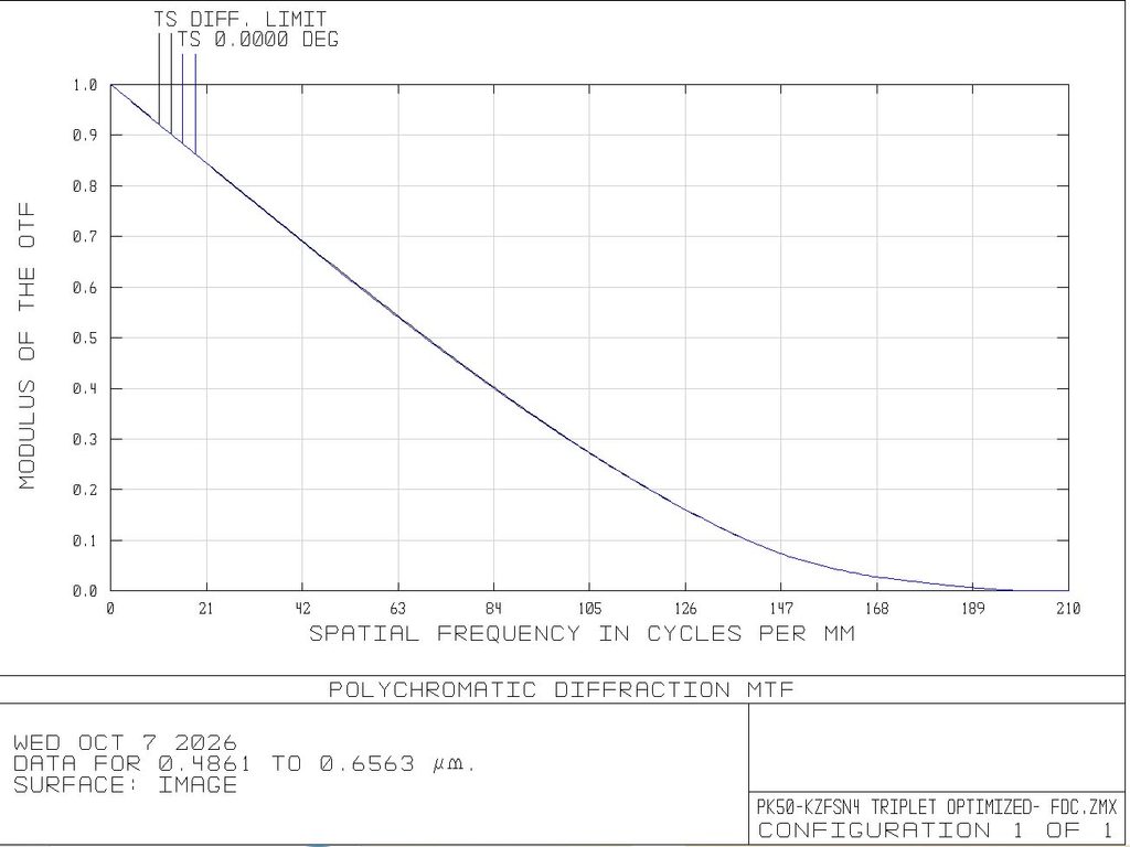
A doublet-like form form is possible by cementing the middle negative KZFSN4 element to the positive BAF4 element. Since their F-C dispersions are nearly equal, changes in the cemented surface radius effect a difference in deviation by the intermediate wavelengths only, thereby offering control over the secondary spectrum.
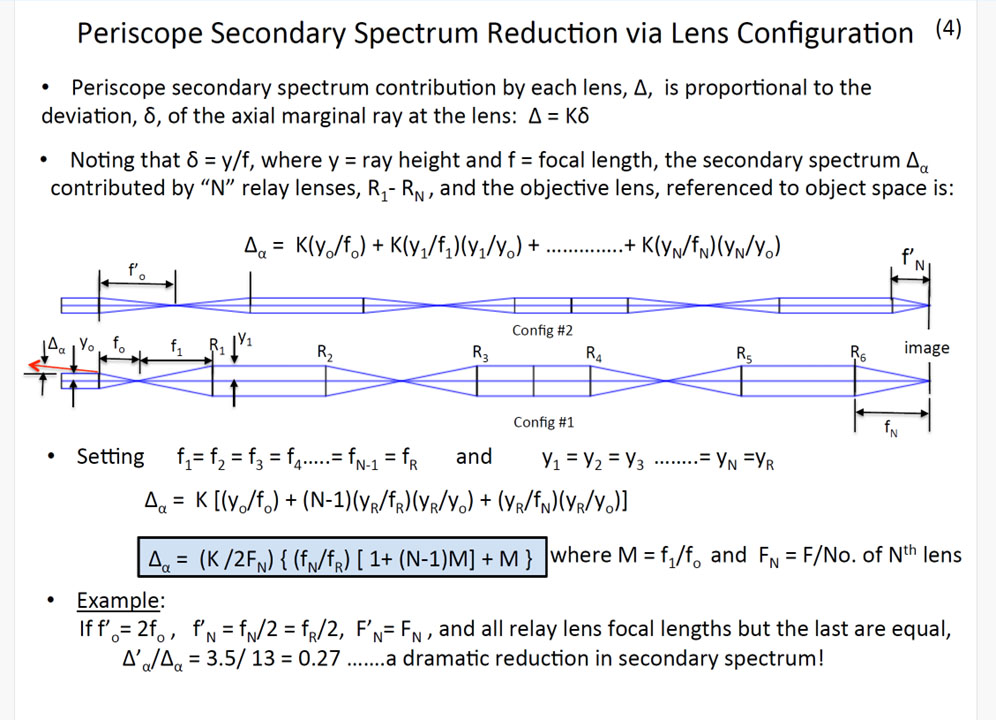
Secondary Spectrum Reduction via Lens Configuration
Glass Specs, Melt Design, First Real Optics Test, Thermal Effects
Melt Design
The very high level of aberration correction in the triplet apochromat example above is necessary if image quality at the focus of the complete train of optics in the periscope is to be near the diffraction limit, say one quarter wave OPD.
Achieving the design performance shown on paper in the actual hardware requires special attention in the glass procurement specifications, lens element manufacture, and lens mounting, and control over the atmospheric and thermal environment surrounding the optics, to the greatest extent possible.
Control of the refractive index in the glass manufacturing process is not practicable in view of the very small deviations allowable, the large number of lens elements in each mast, glass procurement lead times, cost, and the large number of periscopes to be manufactured over the years. All of this resulted in the major, first ever decision to design each set of optics to specific designs based on glass melt data.
Periscope Assembly and Test
Following a very educational meeting in Mainz Gemany with the Schott Glass experts, glass types were decided upon and procured. Lenses were fabricated in house, assembled into high precision lens housings, optimized for minimum wavefront error via lens element rotation about their axes, and aligned on a 50-foot-long rail in the shop. A collimator with pinhole light source at its focal point directed light into the periscope. A microscope was set up at the lower end and focused on the image at the focal point of the last relay lens.
Would the wavefront passing through fifty-two lens surfaces be preserved sufficiently? Our goal was a quarter wave optical path difference. Would we achieve the apochromatic color correction we had on paper? Would the random imperfections incurred at each lens surface fortuitously average out to a low OPD or on the other hand pile up?
Our first indication came from the man seated at the microscope, Dr. Robert Hopkins , who was visiting for the occasion. We witnessed a “WOW!” from him as he placed his eye at the microscope eyepiece, while the rest of us present would wait our turn to witness this historical event, a nearly diffraction-limited periscope image over the full visible spectrum ……a white, textbook-like Airy disc!
Thermal Effects
Thermal effects on periscope optical performance consist of the uncontrollable factors, especially atmospheric effects on the light path between the periscope and the viewed object, and the controllable factor , especially the heat generated within the periscope. The latter is addressed here.
Heat is generated within the periscope mast by motor drives for moving focusing lenses and switching magnification change optics. In the periscope head heat is generated by motor drives of the head prism for line of sight control and image motion compensation, switching field of view change optics, and to a much larger extent by the head window de-icing and demisting heater.
Heat within the mast can distort both the lens geometry and glass homogeneity via thermal expansion and contraction, the air surrounding the lens being similarly affected.
Since heat sources are generally localized off the lens centerline, incurred wavefront distortions are asymmetrical about the centerline resulting in corresponding distortion of the star image, the building block for the entire image.
Control of the heat begins with prudent design concepts like using mechanical means in lieu of electrical means wherever possible; for example, to hold a lens in position, not allowing the continuous operation of the associated lens positioning drive motor. And the obvious means of activating electrical devices only when absolutely essentiual, like deicing or demisting the head wundow, and allowing sufficient thermal stabilizing time after the heat source is deactivated.
The U.S. Navy Type 18 Periscope Program
The U.S. Navy’s specification for a periscope having the highest possible photographic resolution drove Kollmorgen to quickly upgrade its capabilities to become competitive with the large aerospace companies that were specializing in aerial and satellite reconnaissance systems utilizing, their own advanced optical design computer software. They were obvious contenders for the Type 18 Periscope.
Kollmorgen needed to quickly fill the enormous gap in optical design software, being presently restricted by the primitive code and hardware available on the LGP-30 computer.
In a remarkable coup carried out by Kollmorgen management, the gap was quickly reduced by purchasing the rights to CODE3 optical design software of Optical Research Associates (ORA). This was the first and only such arrangement by ORA, allowing Kollmorgen to achieve immediately what would take years to develop on their own, and, of course, that time was not at all possible now with the Type 18 critical need now facing them.
In addition, a state-of-the art mainframe computer, the SDS 930, was purchased.
An expert optical engineer from Delft University was brought on board and under his direction dozens of relay lenses utilizing special glasses, i.e. glasses, with favorable partial dispersion characteristics were designed. A short list of candidate glasses was prepared, followed by a visit to the Schott optical glass facility in Mainz Germany to learn about the glasses’ optical , mechanical, chemical and thermal properties,
Immediately folloeing the Schott visit, the engineering, procurement, manufacturing and quality managers met and agreed on the glass types, the specifications were prepared, the order made and delivery awaited.
As discussed above, the periscope was then successfully built and tested.
Armed with this superb periscope, Kollmorgen, after extensive field tests at sea, won out against its rivals, taking a big step to ensuring the company’s survival for years to come……a come-from-behind win , a modern-day David and Goliath story!
Much deserved accolades go to the entire Kollmorgen team, from top management who funded and directed the effort, to all the workers “in the pits” who worked very long hours for many weeks earning their survival.