Compact Video Rate Optical Scanner
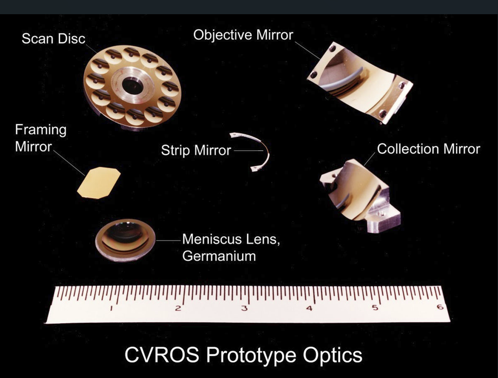
The diamond-turned CVROS mirror components and meniscus window of the prototype scanner shown in the page “Periscopoe IR Imaging” are repeated here for convenience, as are the ray diagrams which follow.
The configured components of CVROS ate shown in the ray trace diagrams below, plan view on top, elevation view below.
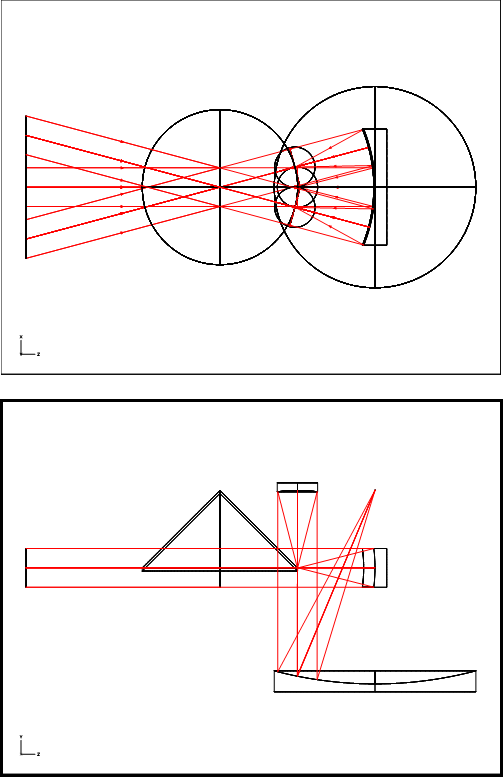
In the plan view, the system point of concentricity is seen to lie at the center of curvature of the objective mirror located on the right, and coincides with the entrance pupil point for the optics which follew.
All entering rays are focused by the objective mirror onto the strip mirror, a thin slice of a right circular cone of 45 degrees half-angle. The incident pencils of rays on the strip mirror are reflected upward 90 degrees toward a concave reflector, or “:dimple”, embedded into the surface of the scan disc, one of a dozen such “dimples” which have been machined into on the disc in a circular pattern.
The reflected pencils of rays are cones of height equal to the focal length of the dimples in the scan disc. The disc rotates about an axis that passes through the system point of concentricity, the same axis as the strip mirror. The pencils become collimated light bundles after reflection , collected by the collection mirror and focused onto a detector element, as shown in the elevation view below.
The detector element length and width define the instantaneous field of view of the system, i.e., the building block for the area image. It receives light from each pixel in the image sequentially, at video rate, as the scan disc rotates. When the dimple has traversed the full arc length of the strip mirror the scan of a line in the object. has been completed. The process is repeated by the next dimple. allowing either overscan or advancement to the adjacent line in the object by way of an oscillating framing mirror positioned at the entrance pupil.
Click on the Dropbox link below to access a PowerPoint presentation on CVROS, Compact Video Rate Optical Scanner. Press “Continue” on the dialog screen. Select “Slide Show” and then “From Beginning”: Press the ” dowm arrow” button to advance through the slides. On completion close the PowerPoint tab and return here to the main site.
The development of diamond turning at Kollmorgen is summarized in the following article by Herbert Torberg who pioneered its development within the overall optical industry.
CVROS became the foundation of the MicroFlir, Kollmoregen’s first thermal imaging product, The MicroFlir was the core product a new subdivision based in Keene, N.H..Details of the MicroFlir thermal imager appear on the page “MicroFLIR”.
The CVROS scanner has application beyond infrared imaging.. It can be used in reverse as a laser writer and because it comprises mirrors in lieu of lenses can be used in spectrums outside the visible spectrum concurrently with the visible spectrum. Application development is required in these areas.