Background
Not long after the Type 18 saga, while resting at my desk during the lunch hour my phone rang- quite unusual. It was my boss, Herb Torberg, Director of Engineering calling from the office of the company president, Jim Callahan, asking me to drop down and meet with them. Of course, I did. With minimal pleasantries exchanged, I was immediately asked if I knew what the lettering on the plaque sitting on the president’s desk meant: YCDBSOYAIN. I had no idea. They explained: “You Can’t Do Business Sitting On Your Ass In Northampton”.
This was the prologue to their message that followed: “Get out of the office….. go out and learn about what’s going on in technologies essential for future sub periscopes. I was given no further guidelines, no budget or administrative constraints of any kind…. a great expression of trust and confidence.
The direction to go was quite apparent. My readings of the trade periodicals and various mailings had been giving me that direction: infrared imaging. Thermal imagers were already fielded on military aircraft, ground vehicles and surface vessels at sea but not yet submarines. We were very far behind the curve.
Background, where to begin
Several big aerospace companies were already well established in the infrared field having been developers of infra detectors and imaging arrays, as I learned from our new membership and attendance at the Infrared Symposia. These meetings were conducted periodically during the year by the U.S. Government’s Ft. Belvoir Night Vision Labs at various government facilities throughout the country. The sessions were classified dealing with the state-of-the infrared imaging sensors and their applications in military devices. Note taking was not allowed. The classified proceedings were sent to the attendee’s facility and placed under lock and key, available to members of the organization with a SECRET clearance.
We were beginning to learn about IR technology, but we did not have any past infrared experience. We also lacked the key component, infrared detectors. There was no way we could match the large aerospace companies with their enormously expensive development of infrared detector arrays, the Common Module.
Common Modules employed linear detector arrays comprising many individual detector elements and were scanned by an oscillating mirror to form an area image. The packaged Module size was far too large to be housed within the periscope head. Therefore, an infrared image development had to be based on a simple, available detector.
An infrared imager based on a simple single element detector, was being offered by at least two aerospace contractor and a smaller infrared systems company, FLIR Systems, which had their own detector source. But even these serial scan thermal imagers were far too big to put into the head of a periscope. They also were notoriously unreliable making them absolutely unacceptable for submarine periscopes for obvious reasons
The failures were mostly due to the failure of the vacuum housing in which a high-speed rotating polygon prism was housed. The vacuum housing was necessary to remove the air which prevented the rotating prism from achieving the necessary high video rate scan.
CVROS
These issues gave rise to a totally new concept in high-speed serial scanners: CVROS , a Compact Video Rate Optical Scanner, the basis for a very small, compact infrared camera that can be housed in the head of a submarine periscope.
Diamond turning of optics was being developed at this time by Kollmorgen under the leadership of Herbert Torberg , Director of Engineering, expert in the field of precision engineering.
Unusual mirror optics became possible through diamond turning. This capability combined with the need to image in the infrared spectrum, presently the 8-12 micron waveband, achieve video rate scanning without vacuum housing and the essential requirement to fit into the head of a periscope, a softball-like envelope size, drove the optical design concept thinking in a new direction: folded mirror optics.
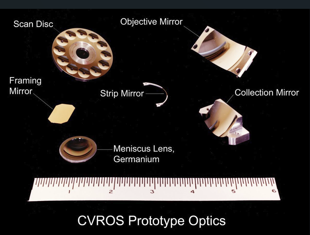
Foremost among the mirror optics came the scan disc. A rotating thin disc would not be burdened by the large air resistance of competing rotating prism systems. Further, by incorporating a circular array of a dozen concave reflectors on the disc, the disc speed to achieve video rates in the image data stream could be held down to about 40,000 revolutions per minute, a feasible number.
A necessary complementary component, the strip mirror, provides the means to capture the focused light from the concave reflectors of the scan disc. and redirect it towards a detector by means of a collection mirror.
The main CVROS optical components are shown below: the scan disc with a circular array of concave reflectors, sometimes referred to as “dimples; ” the strip mirror, a thin slice out of a conical reflector; an objective mirror; a collection mirror that focuses onto a detector; a framing mirror that converts line scans into an area image; and finally a meniscus window which protects the optics and maintains a uniform homogenous local atmosphere and also corrects the spherical aberration of the system, when spherical surfaces for the scan disc are employed in lieu of aspheric.
A detailed comprehensive description of the CVROS concept appears on the page “CVROS”.
The configured components of CVROS ate shown in the ray trace diagrams below, plan view on top, elevation view below.
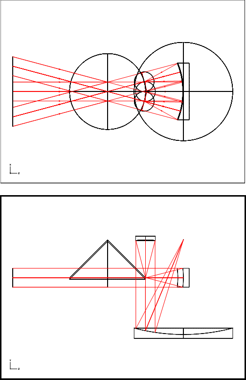
In the plan view, the system point of concentricity is seen to lie at the center of curvature of the objective mirror located on the right and coincides with the entrance pupil point for the optics which follow.
All entering rays are focused by the objective mirror onto the strip mirror, a thin slice of a right circular cone of 45 degrees half-angle. The incident pencils of rays on the strip mirror are reflected upward 90 degrees toward a concave reflector, or “:dimple”, embedded into the surface of the scan disc, one of a dozen such “dimples” which have been machined into on the disc in a circular pattern.
The reflected pencils of rays are cones of height equal to the focal length of the dimples in the scan disc. The disc rotates about an axis that passes through the system point of concentricity, the same axis as the strip mirror. The pencils become collimated light bundles after reflection , collected by the collection mirror and focused onto a detector element, as shown in the elevation view below.
The detector element length and width define the instantaneous field of view of the system, i.e., the building block for the area image. It receives light from each pixel in the image sequentially, at video rate, as the scan disc rotates. When the dimple has traversed the full arc length of the strip mirror the scan of a line in the object. has been completed. The process is repeated by the next dimple. allowing either overscan or advancement to the adjacent line in the object by way of an oscillating framing mirror.
These unique optical components were manufactured for the first time by the recently developed diamond turning equipment and process, with facili6ies in Wallingford, Ct. and later in Keene, N.H.. They were then assembled into a housing with the detector and cooler. m and supporting electronics to create the proof=of-concept model for testing in the lab.
It was a most memorable historic even for Kollmorgen. A small group of us including Herb Torberg huddled around this prototype thermal imaging camera in a darkened room and viewed on a television monitor the image of a person’s breath while he sipped a hot drink. “Outstanding!” came the cry from Herb, a normally very reserved individual.
In a period of just thirteen months, we had transitioned from having nothing but paper to a working thermal imaging system! The engineering work was carried out by our existing Advanced Technology group of just six individuals, including myself. No outside “experts” were bought in….we made do with what we had, which proved to be enough.
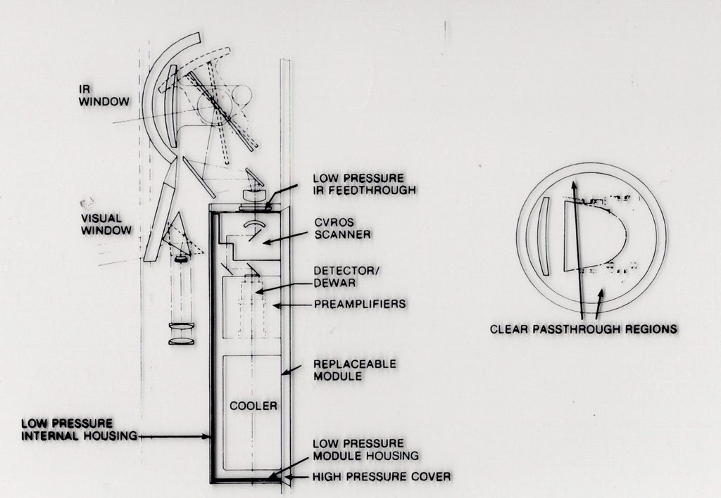
Below is shown the CVROS configured in the head of a periscope together with visual optics making a dual spectrum device, concurrent visual and IR imagery.
The word of our success spread. A relative of a person working at Kollmorgen, learned about it and relentlessly pursued a job with us. We finally hired him, Gerry Ouellette, as our advanced technology marketer. He visited and made presentations at the Night Vision Labs at Fort Belvoir, VA, Redstone Arsenal in Huntsville, Al, and various other military facilities in the U.S..
Gerry had contacts at DARPA (Defense Advanced Research Project Agency) and met with them. Shortly afterwards, an article on CVROS and its thermal imaging applications appeared in Aviation Weekly, a highly respected and widely read publication on military and space technology and programs.
Technical papers* were prepared and delivered to the Infrared Image Symposia (IRIS), one by Ted Strzempko, our systems engineer who addressed the electronics, and one by myself on the scanner optics. These papers formally documented the project and got the word out to the entire infrared community.
Soon afterwards , inquiries on employment at Kollmorgen began to arrive. Chief among these were those from one of the large aerospace companies with inferred technology. An infrared project leader there with a foothold on existing government programs was hired and he led a transition to our company of several leading, experienced engineers.
The new group, located at the company’s site in Keene, N.H., were soon awarded a major government contract. The group rapidly expanded and now included the company’s diamond turning operations. They refined and expanded the scope of the original CVROS, developing the MicroFlir. See same named page on this web site.