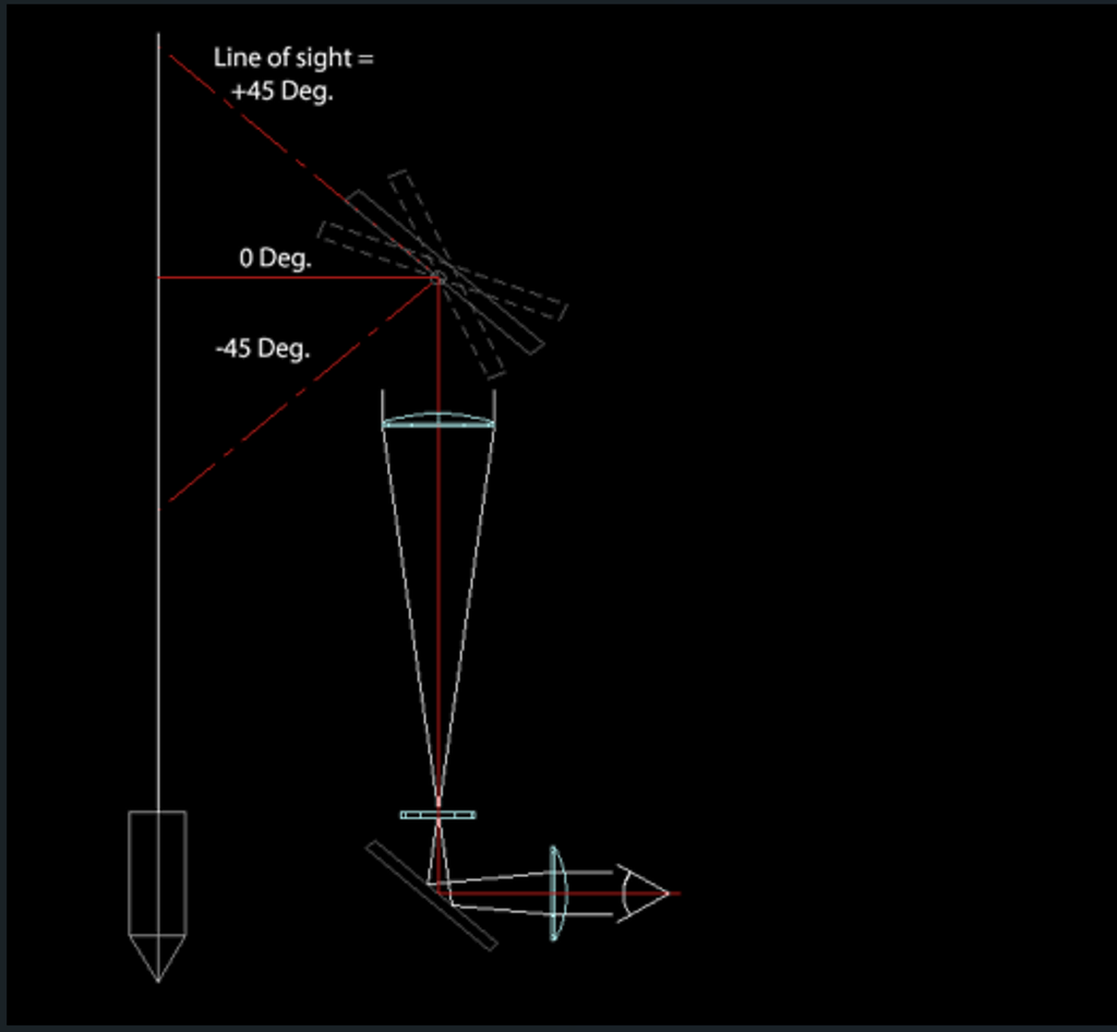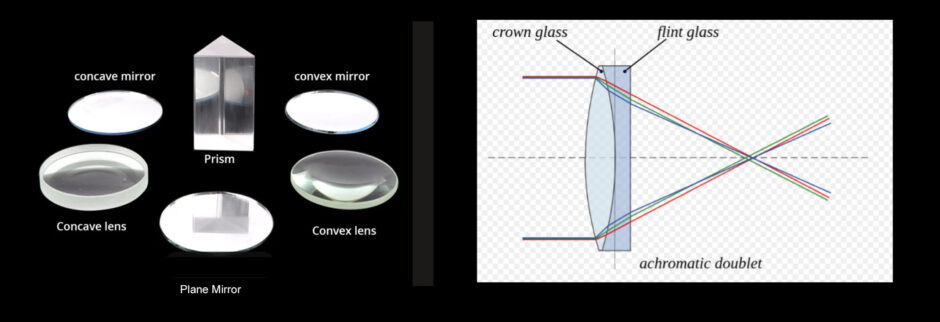
Many military ground vehicles incorporate optics for viewing and sighting which are closely akin to submarine periscope optics. Both comprise an objective lens, relay lenses, eyepiece, and folding mirror or prism at the top and one at the bottom of the instrument.
Vehicle sights, in addition, typically include several folding mirrors to direct the optics line of sight from a small entrance window on the vehicle to the operator’s eye., usually on a zigzag course dictated by the geometrical configuration of the vehicle.
One such configuration is shown in the link below. It is an advanced sight design which incorporates a laser rangefinder, image intensiifer, sun sensor and dual eyepiece channels to allow simultaneous viewing by two operators.

Special attention in such sights is given to acquiring and maintaining correct image orientation in the presence of multiple mirror folds.
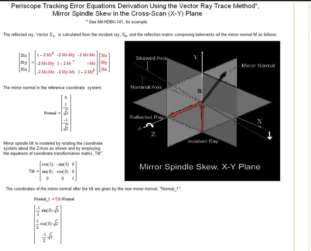
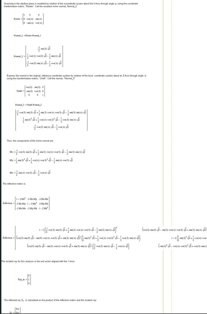
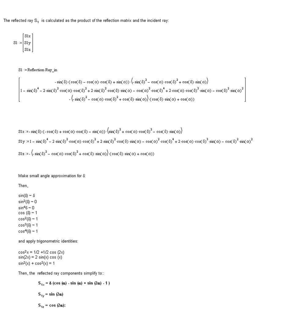
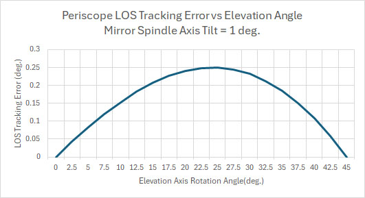
Also, minimizing tracking errors as the line-of sight is slewed in elevation and azimuth is key since this determines whether a target will be hit or missed. Tracking error here is defined as the difference between the actual angular position of an object and the position indicated by the central point on the sighting reticle.
Image orientation
Determining image orientation in an optical system comprising fold mirrors is relatively easy if the arrangement of mirrors is orthogonal. When such is not the case help can be offered using the technique described in the presentation found at the following link.
Line of sight tracking errors